Computer Controlled Cutting
This week was focused on learning and practicing different type of Computer-Controlled cutting practices.This week there are two types of assignments; one group and one individual.
-
Group assignment
Characterize your laser cutter’s focus, power, speed, rate, Kerf, joint clearance.
-
Individual assignment:
-
Cut something on the vinyl cutter
- Design, laser cut, and document a parametric construction kit, accounting for the laser cutter kerf, and assembled in multiple ways.
Group Assignment
The Group Assignment page is at the following link Click here
Laser Cutting:-
In STPI- Bhubaneswar fablab have a laser cutter.
Model is Epilog Fusion 32
Following are the few specification of laser cutter Epilog fusion 32:-
-
Maximum Material Thickness-- 14" (101.5 mm)
- Laser Source-30, 40, 50, 60, 75 or 120 watt, CO2, air-cooled, all-metal Waveguide laser tube, 10.6 micrometers.
- Print Driver and Software---Laser Dashboard, Epilog Control Center, and Epilog Job Manager.
- Print Interface--10 Base-T Ethernet or USB connection. Compatible with Windows XP/Vista/7/8/10.
- Air Assist--Attach an air compressor to our included Air Assist to remove heat and combustible gases from the cutting surface by directing a constant stream of compressed air across the cutting surface.
- Operating Modes---Optimized raster, vector or combined modes with engraving and cutting in one job.
- Electrical Requirements------Auto-switching power supply accommodates 110 to 240 volts, 50 or 60 Hz, single phase.
- Size (W x D x H)- 52.5" x 35.5" x 40.75" (1334 x 851 x 1035 mm)
-
Red Dot-Pointer-Since the laser beam is invisible, the Red Dot Pointer on Epilog's Laser Systems allow you to have a visual reference for locating where the laser will fire.
-
Ventilation-650 CFM (1104 m3/hr) external exhaust to the outside or internal filtration system required. There are two output ports, each 4" in diameter.
My activity Summary:-
- In the group assignment I have been going through the vector for cutting and raster for engraving using the
different type materials which has explained in group assignment.
- First thing I have done designing for my individual assignment for press fit. The design should be parametric. I used Solid Works as tools for parametric designing.
- Before parametric designing it needs to emphasize that the design intent using features and constraints, and this allows users to automate repetitive changes.
- In my office is newly constructed and interior work is going on hence I get so many wood martial for laser cutting but for press fit I am using veneer wood.
Neil says well and Sibu has taught me, the laser should
not be left unattended, Safety first. As laser is very sensitive to fire and also a very important that proper
measurement of designing and proper setting of speed, power and frequency as per the material then only do cut
or else it may goes wrong. Every time after finishing of the work, you have to clean the rules, the bee panel
and every so often clean the lens. The extraction of the gases is
done outside, but the proper functioning of the
extractor and the compressor for the air assist must also be checked.
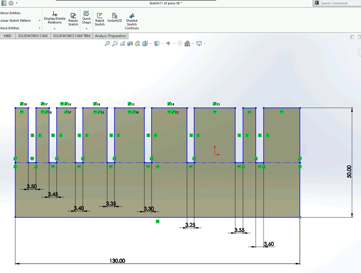
Press-Fit Test:-
My used material thinness is 3.5 mm I did design in solid works for testing of best fit
after vector cut of the material, where I can use the exact measurement in design to do accurate press fit. Here I
have drawn different measurement of cut with difference of .5 mm from my original material thinness i.e. 3.5mm
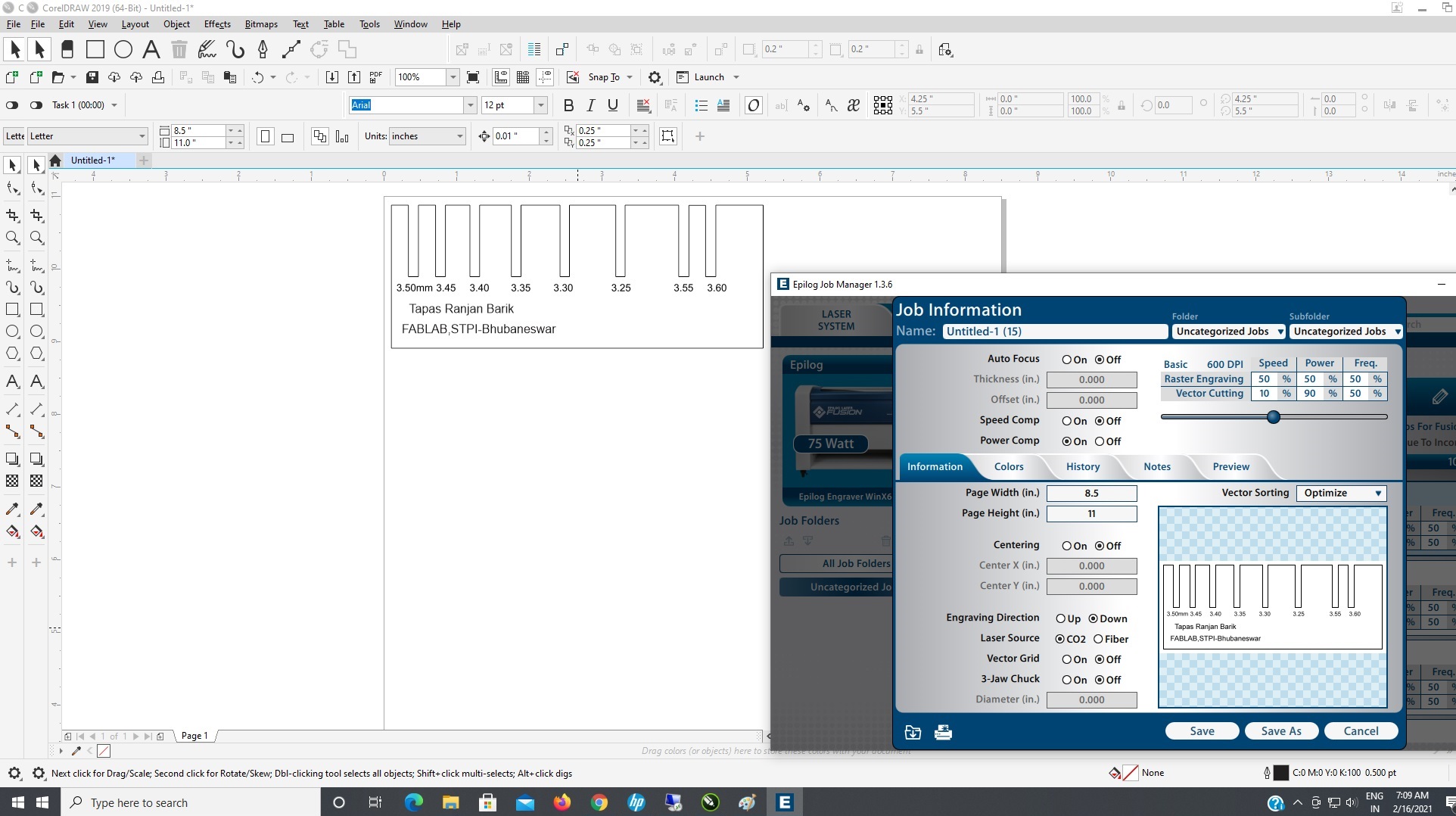
Here is used for vector cutting
Dots per Inch (DPI) -600
Speed -10%
Power -90%
Frequency-50%
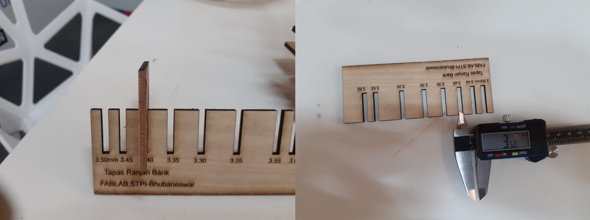
Hence the above activity given me the clear measurement after
cutting for best fit as actually then designing kerf is 3.40mm after cut 3.50mm material
is get best fit which shows that .5mm each side cut by laser. 3.40 mm is the Best fit to do my press fit.
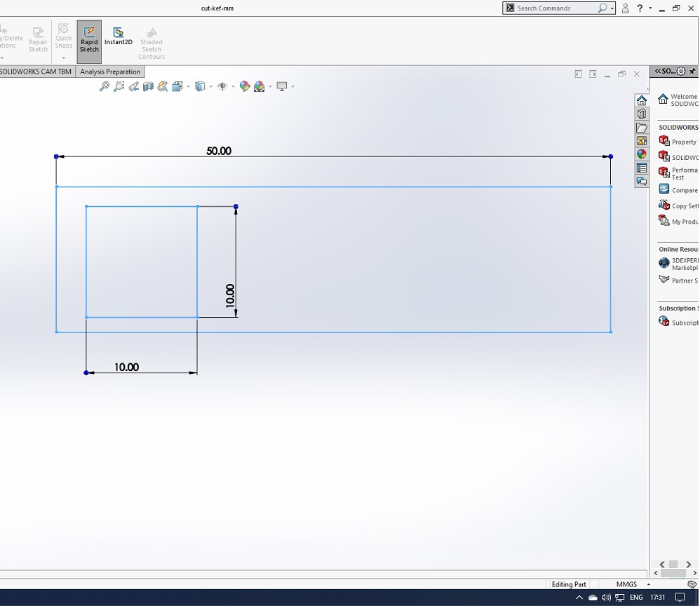
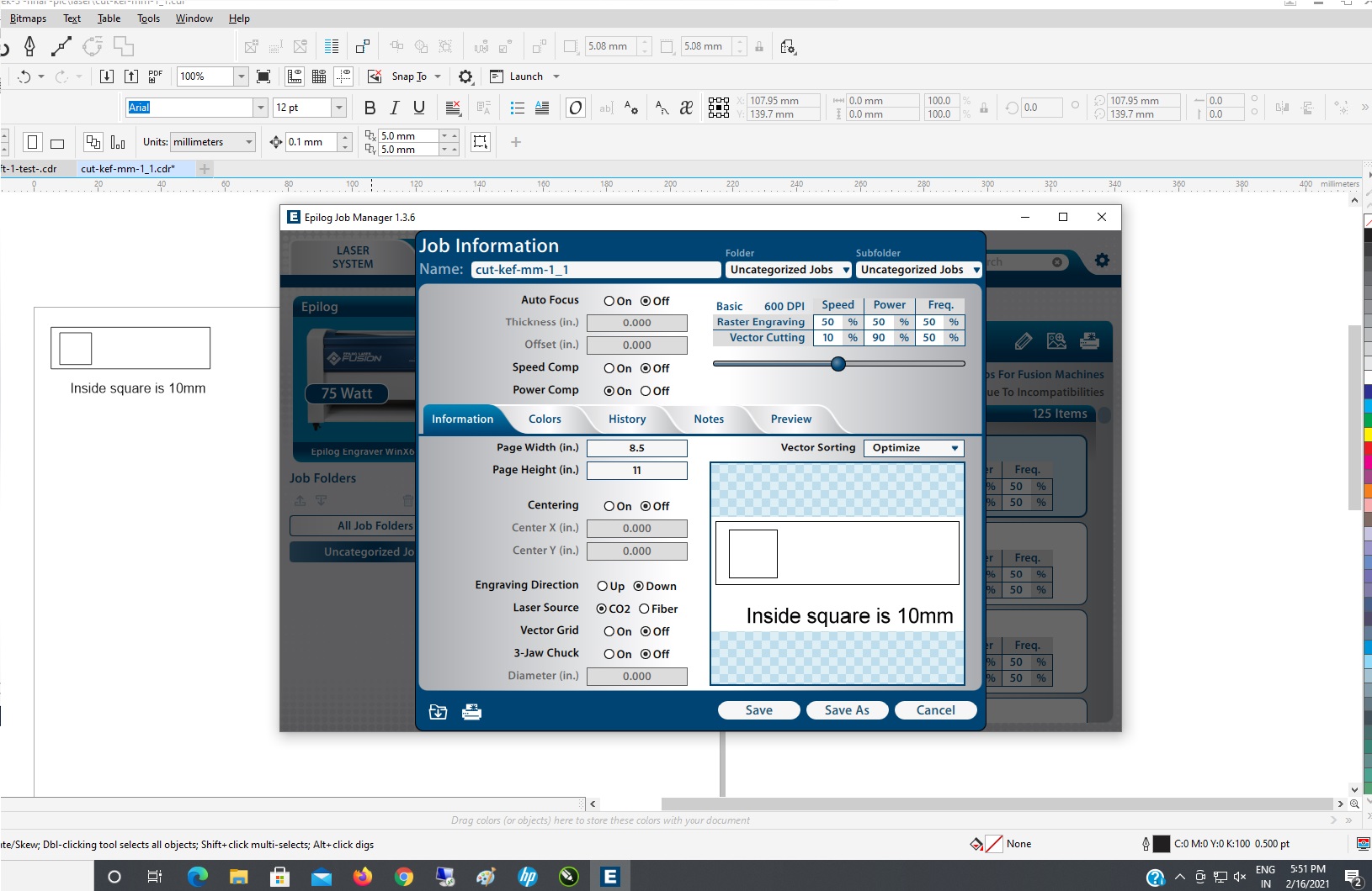
Kerf test:-
After having performed the press-fit test with veneer board, I decided to do a kerf test for veneer wood material of small size as a sample.
I design it with solid works, and in the test I will have a 10mm by 10 mm square to check
the measurements with the caliber.
Here is used for vector cutting
Dots per Inch (DPI) -600
Speed -10%
Power -90%
Frequency-50%
 Outside is getting smaller 9.90 mm
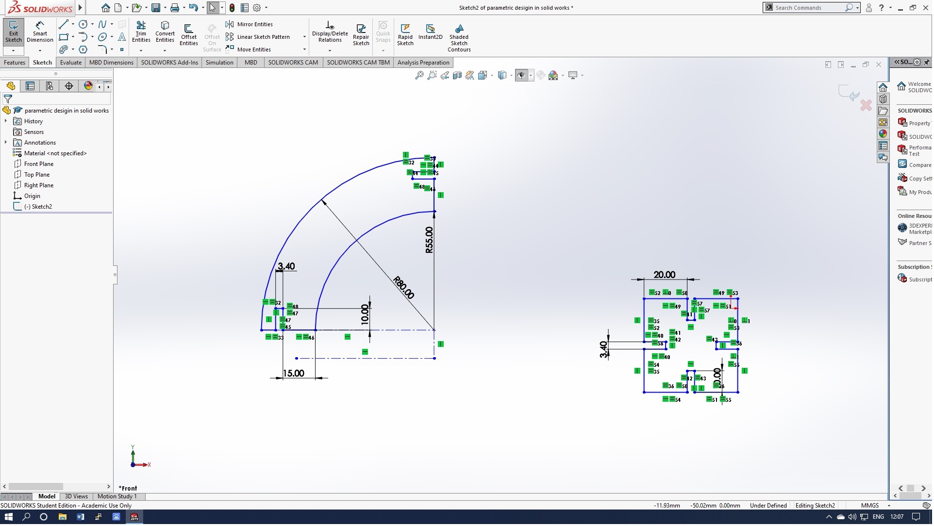
Parametric Designing:-
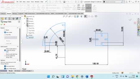
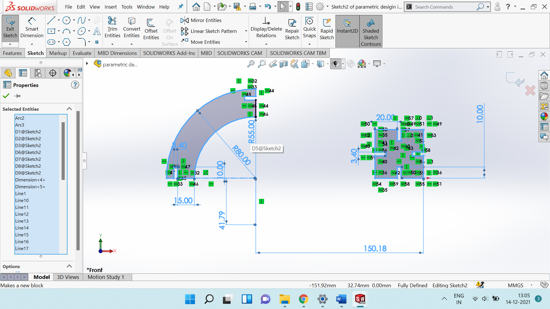
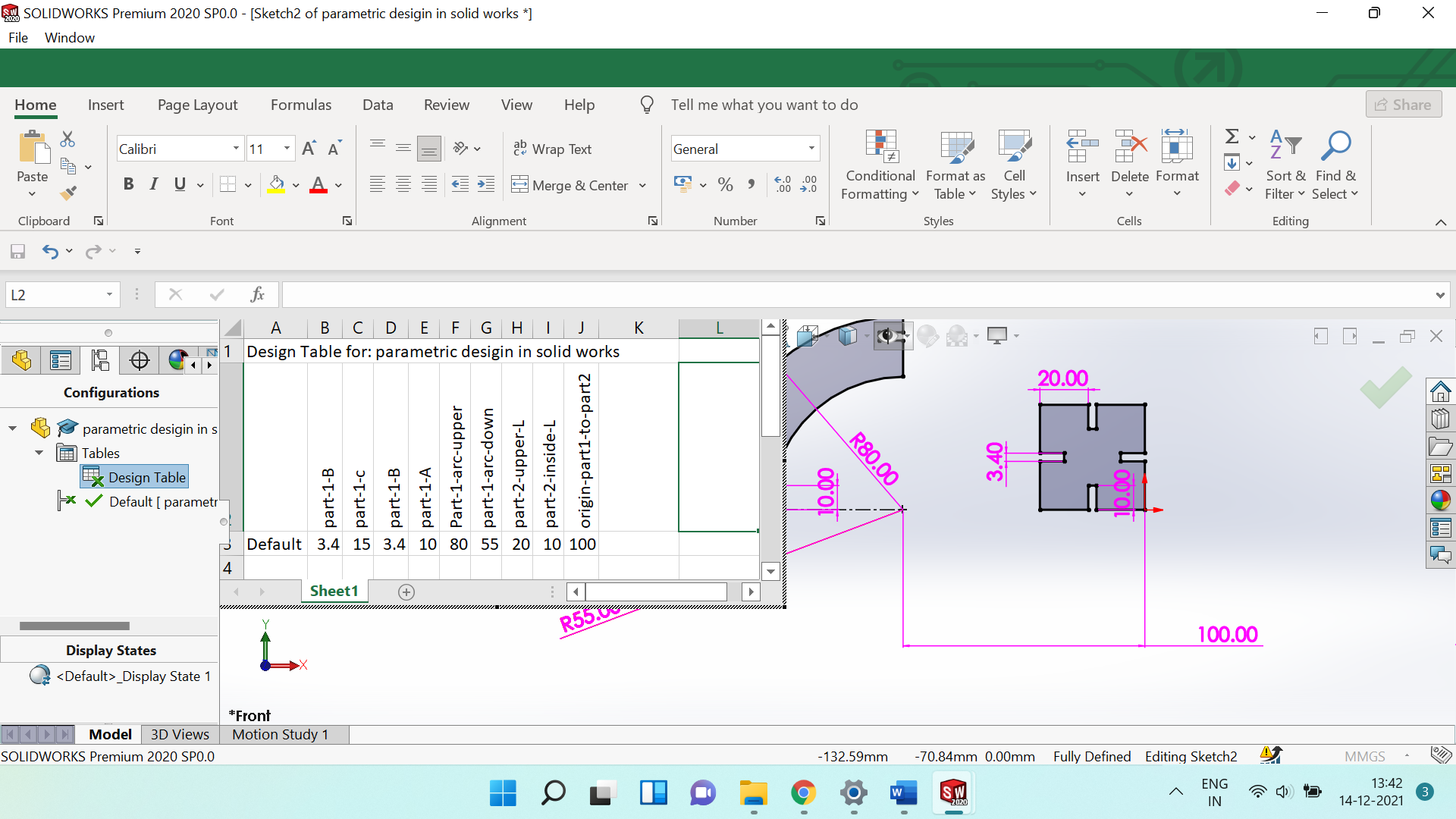
Last week I have going through the different cad tools for 3D designing I am comfortable in solid works. First Sketch draw, two line and arc with radius of 80mm
and 55 mm, both edge of arc joint line then place rectangle of 3.40 mm with and 10mm length and trim as defined in below sketch.

Paremetric designing in modelling means giving constraints to geometrical dimensions or
setting user parameters while designing. When a user parameter changed or modified then the entire geometry shape will get changed.
The tools is very useful for designers and it gives the freedom for the user to modify the final model based on parameters.
The following are the steps involved in parametric design:
First of all, It needs to decide the parameters i.e length, thickness, pressfit, depth, kerf, offset & chamfer as per your desigin.
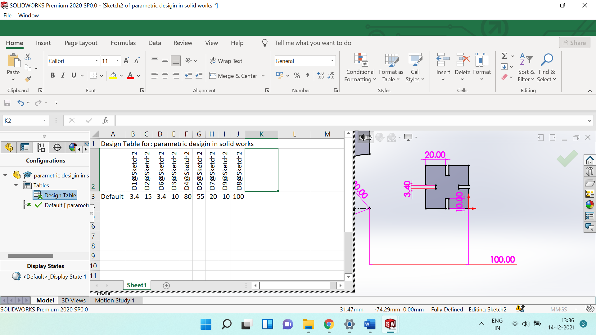
Initial above desigin it was not fully defined i have rectified and make it fully defiend
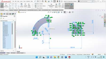
Go to Insert then table opetion there is option design table once click there the excel sheet will be appper there it needs to select parameter name it can me edit
as per your own name as suitbale.
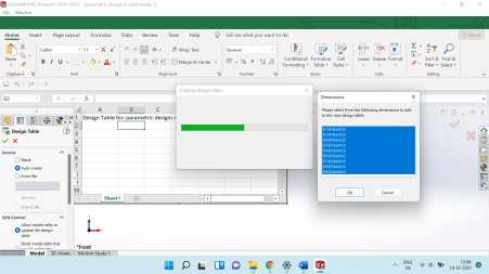
where by default excel design table is there but i have been new desgin table in excel and named as per my design parameter >/p>

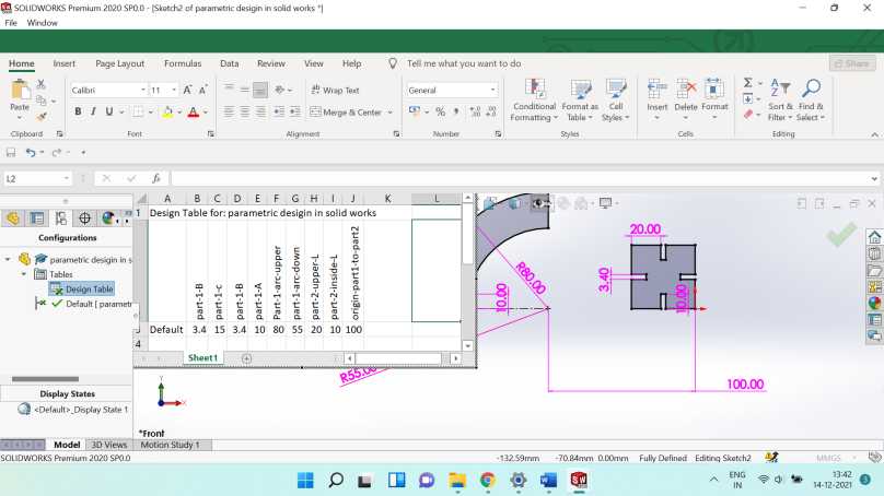
Here i have named and defined the parameter value as per my design in the design table when any parameter change in desigin table the design parameter
be will change here it show its proper parameteric design.
Here I used the same parameter as
in press fit and Kraft test for vector cutting
Dots per Inch (DPI)
-600
Speed -10%
Power -90%
Frequency-50%
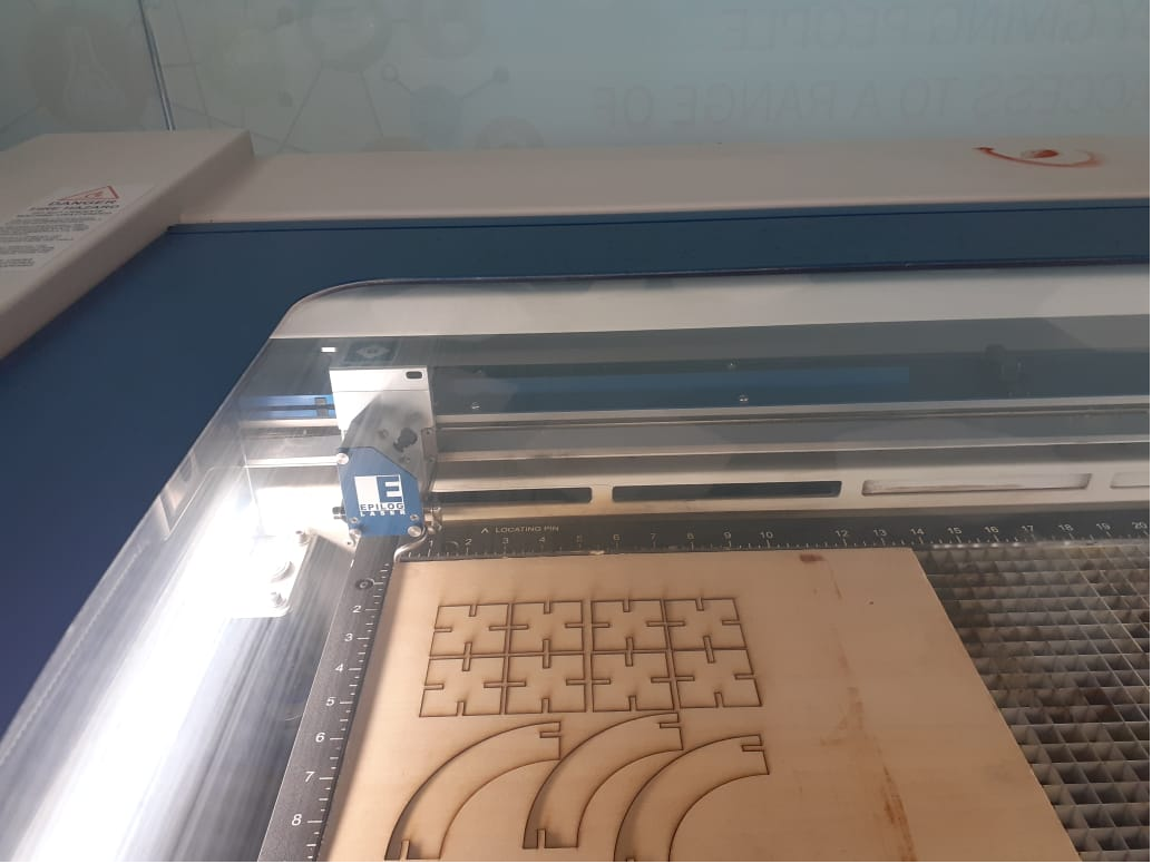

As I have few veneer board of
small size hence I have going through three time
cut. After cutting I arranged in circular and tower shape.
Engraving with color Mapping. i have engraved the MDF with diffenet speed,power and frequency with color mapping

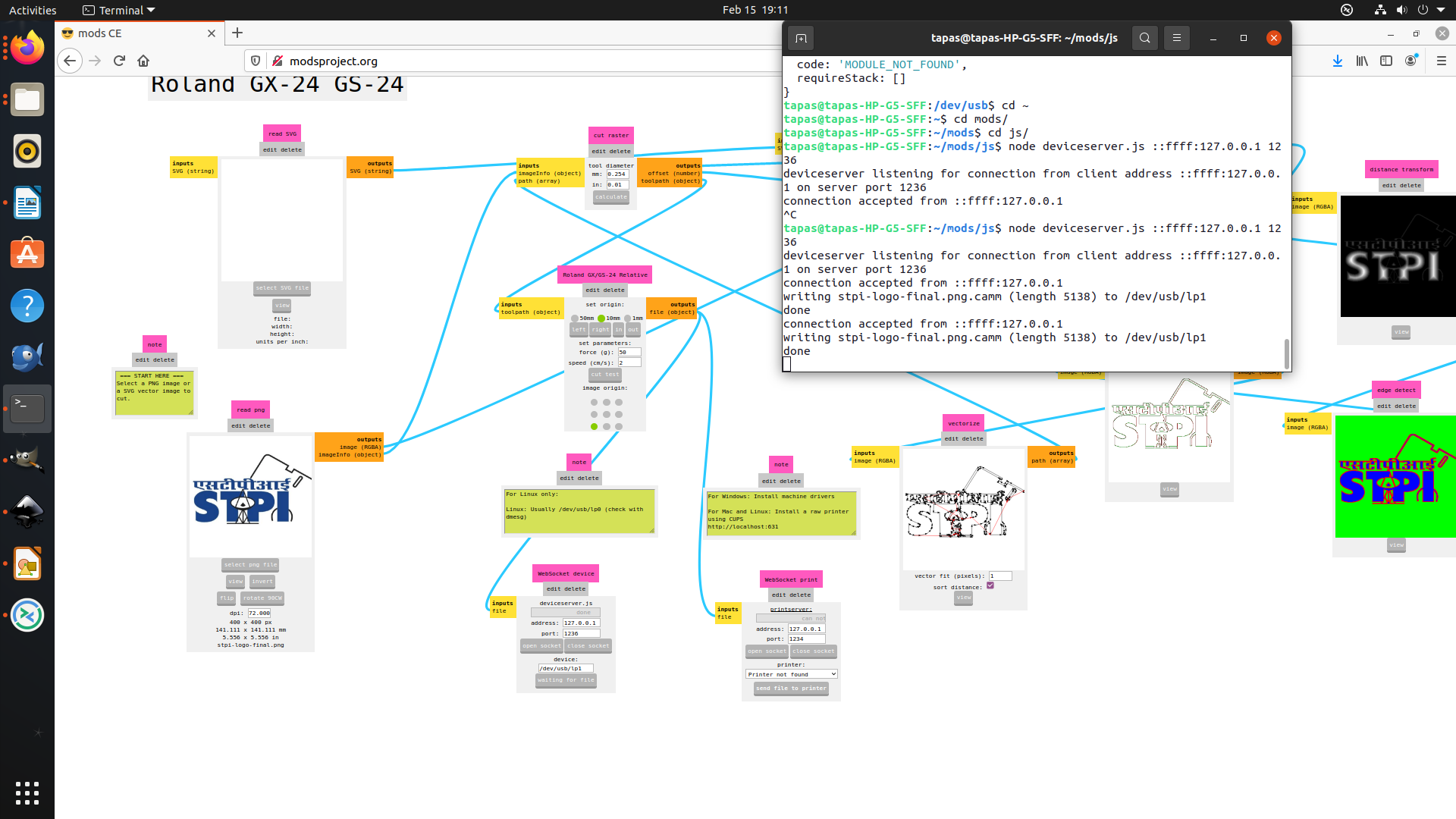
Setting up MODS on Linux
I am using Ubuntu operating system in my pc I installed mods. Cloning the MODS repository and running the local server.
Install the dependencies using the following commands:
sudo apt update
sudo apt install build-essential
curl -o- https://raw.githubusercontent.com/creationix/nvm/v0.34.0/install.sh | bash
piping directly to bash could be harmful
Check whether nvm is installed using command -v nvm
You might need to open a new terminal.
nvm install node
npm install -g http-server printer ws
Install node-gyp and libcups2
sudo apt install node-gyp libcups2-dev
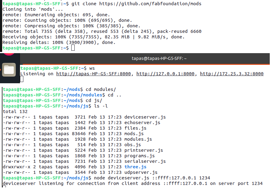
run the command the terminal of js directory of mods node deviceserver.js ::ffff:127.0.0.1 1236
Vinyl Cutting:-
Roland GS-24 Vinyl Cutter is available in STPI-Bhubaneswar fablab
Go to http://modsproject.org/ website then right click open program then open program next click cut for roland GX-GS 24 vinyl cutters two type of
file can support one is svg other is
png.I have png file of stpi logo then select the file uploaded Calculate in cut raster then open socket .
Then send the file to the vinyle cuttter. the penforce is 50 gf and speed is 20cm/s.
Before send the file to the machine it needs to chack the vinyl knife and set the origin.


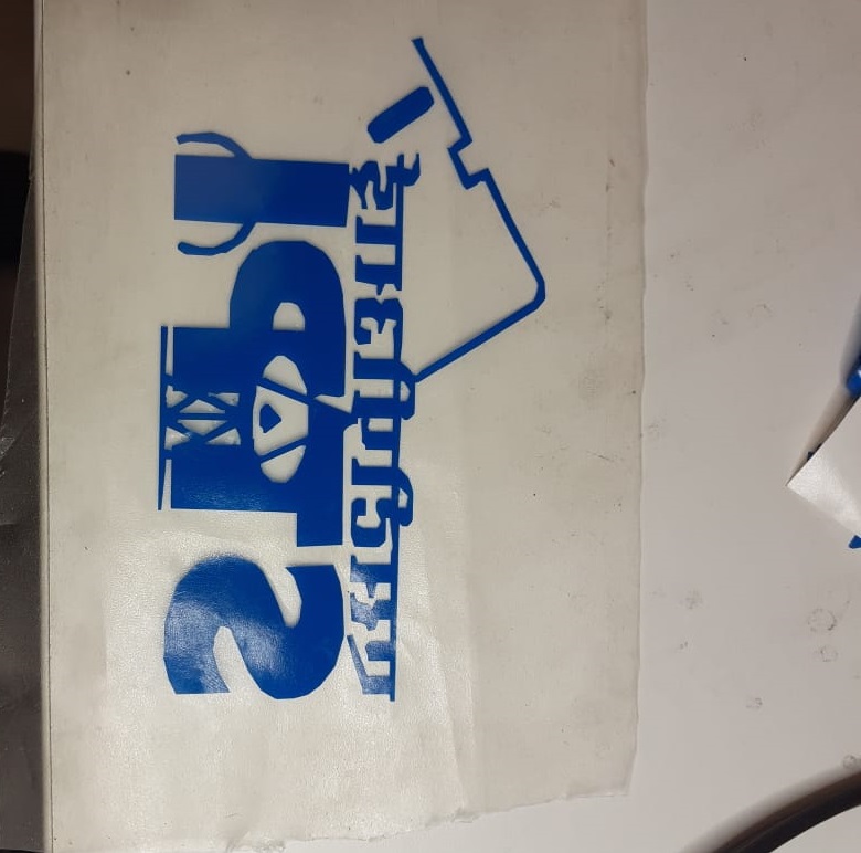

After cutting, flex is used over my cut vinyl and press properly then remove flex
rolling, few tiny cutting materials are rest I used tweezers to remove it then
the clean and press the vinyl in my desk in my office.
Click to download the files :
This week was focused on learning and practicing different type of Computer-Controlled cutting practices.This week there are two types of assignments; one group and one individual.
-
Group assignment
Characterize your laser cutter’s focus, power, speed, rate, Kerf, joint clearance.
-
Individual assignment:
-
Cut something on the vinyl cutter
- Design, laser cut, and document a parametric construction kit, accounting for the laser cutter kerf, and assembled in multiple ways.
Group Assignment
The Group Assignment page is at the following link Click here
Laser Cutting:-
In STPI- Bhubaneswar fablab have a laser cutter.
Model is Epilog Fusion 32
Following are the few specification of laser cutter Epilog fusion 32:-
-
Maximum Material Thickness-- 14" (101.5 mm)
- Laser Source-30, 40, 50, 60, 75 or 120 watt, CO2, air-cooled, all-metal Waveguide laser tube, 10.6 micrometers.
- Print Driver and Software---Laser Dashboard, Epilog Control Center, and Epilog Job Manager.
- Print Interface--10 Base-T Ethernet or USB connection. Compatible with Windows XP/Vista/7/8/10.
- Air Assist--Attach an air compressor to our included Air Assist to remove heat and combustible gases from the cutting surface by directing a constant stream of compressed air across the cutting surface.
- Operating Modes---Optimized raster, vector or combined modes with engraving and cutting in one job.
- Electrical Requirements------Auto-switching power supply accommodates 110 to 240 volts, 50 or 60 Hz, single phase.
- Size (W x D x H)- 52.5" x 35.5" x 40.75" (1334 x 851 x 1035 mm)
-
Red Dot-Pointer-Since the laser beam is invisible, the Red Dot Pointer on Epilog's Laser Systems allow you to have a visual reference for locating where the laser will fire.
-
Ventilation-650 CFM (1104 m3/hr) external exhaust to the outside or internal filtration system required. There are two output ports, each 4" in diameter.
My activity Summary:-
- In the group assignment I have been going through the vector for cutting and raster for engraving using the different type materials which has explained in group assignment.
- First thing I have done designing for my individual assignment for press fit. The design should be parametric. I used Solid Works as tools for parametric designing.
- Before parametric designing it needs to emphasize that the design intent using features and constraints, and this allows users to automate repetitive changes.
- In my office is newly constructed and interior work is going on hence I get so many wood martial for laser cutting but for press fit I am using veneer wood.
My used material thinness is 3.5 mm I did design in solid works for testing of best fit after vector cut of the material, where I can use the exact measurement in design to do accurate press fit. Here I have drawn different measurement of cut with difference of .5 mm from my original material thinness i.e. 3.5mm
After having performed the press-fit test with veneer board, I decided to do a kerf test for veneer wood material of small size as a sample. I design it with solid works, and in the test I will have a 10mm by 10 mm square to check the measurements with the caliber.
Last week I have going through the different cad tools for 3D designing I am comfortable in solid works. First Sketch draw, two line and arc with radius of 80mm and 55 mm, both edge of arc joint line then place rectangle of 3.40 mm with and 10mm length and trim as defined in below sketch.
Paremetric designing in modelling means giving constraints to geometrical dimensions or setting user parameters while designing. When a user parameter changed or modified then the entire geometry shape will get changed. The tools is very useful for designers and it gives the freedom for the user to modify the final model based on parameters. The following are the steps involved in parametric design: First of all, It needs to decide the parameters i.e length, thickness, pressfit, depth, kerf, offset & chamfer as per your desigin.


Dots per Inch (DPI) -600
Speed -10%
Power -90%
Frequency-50%
Install the dependencies using the following commands:
sudo apt update
sudo apt install build-essential
curl -o- https://raw.githubusercontent.com/creationix/nvm/v0.34.0/install.sh | bash
piping directly to bash could be harmful
Check whether nvm is installed using command -v nvm
You might need to open a new terminal.
nvm install node
npm install -g http-server printer ws
Install node-gyp and libcups2
sudo apt install node-gyp libcups2-dev
Roland GS-24 Vinyl Cutter is available in STPI-Bhubaneswar fablab
Go to http://modsproject.org/ website then right click open program then open program next click cut for roland GX-GS 24 vinyl cutters two type of file can support one is svg other is png.I have png file of stpi logo then select the file uploaded Calculate in cut raster then open socket . Then send the file to the vinyle cuttter. the penforce is 50 gf and speed is 20cm/s. Before send the file to the machine it needs to chack the vinyl knife and set the origin.